|

 
| |
Card Enclosure Diagrams
For use by authorized service providers.
This page includes a table with links to diagrams and tables for Model 270 by
feature codes. If you need address information, refer to
Addresses -- Model 270.
Table 1. Model 270 diagrams and tables by processor feature code
Find the processor feature code you are working with, and then select the
adjacent table or figure for details.
| Processor feature code |
Locations diagram |
FRU positions and failing components |
Network Interface Controller (NIC) is in
this FRU |
Processor is in this FRU |
HSL loop number and port information |
| 22A2, 22A4, 22A5, 2301, 2302, 2422 |
See
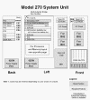
Figure 1. Model 270 system unit, processor features 22A2, 22A4, 22A5,
2301, 2302, 2422 (Processor embedded on backplane) |
See
Table 3. FRU locations and failing components for Model 270 (Processor
features 22A2, 22A4, 22A5, 2301, 2302, 2422) |
Embedded in the system unit backplane in
position MB1 |
Embedded in the system unit backplane in
position MB1 |
Loop number 256 has external HSL ports
labeled "A0" and "A1" |
| 22A7, 22A8, 22AA, 22AB, 23F4, 23F5, 2423,
2424, 2454 |
See
Figure 2. Model 270 system unit, processor features 22A7, 22A8, 22AA,
22AB, 23F4, 23F5, 2423, 2424, 2454 |
See
Table 5. FRU locations and failing components for Model 270 (Processor
features 22A7, 22A8, 22AA, 22AB, 23F4, 23F5, 2423, 2424, 2454) |
Embedded in the processor card in position
M02 |
Embedded in the processor card in position
M02 |
Loop number 256 has external HSL ports
labeled "A0" and "A1" |
| 23E7, 23F0, 23F1, 2452 |
See
Figure 3. Model 270 system unit, processor features 23E7, 23F0, 23F1,
2452 (Processor embedded on backplane) |
See
Table 7. FRU locations and failing components for Model 270 (Processor
features 23E7, 23F0, 23F1, 2452) |
Embedded in the system unit backplane in
position MB1 |
Embedded in the system unit backplane in
position MB1 |
Loop number 256 is an internal loop
embedded in the system unit backplane. The loop goes from the NIC, to
the embedded HSL I/O bridge, and back to the NIC with no external HSL
ports. Loop number 257 has external HSL ports labeled "A0" and "A1" |
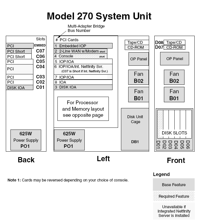
Figure 1. Model 270 system unit, processor
features 22A2, 22A4, 22A5, 2301, 2302, 2422 (Processor embedded on backplane)

Notes:
- The model 270 system unit contains one system PCI bus with one
multi-adapter bridge. The bus number is 0001.
- There is an embedded CFIOP in the system unit backplane in position MB1.
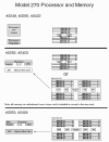
- Memory DIMMS are placed in pairs when more than one DIMM is present. Use
the order A-B, C-D, E-F, then G-H.
- The following table provides information necessary to identify the IOP
to which IOAs are assigned.
Table 3. FRU locations and failing components for
Model 270 (Processor features 22A2, 22A4, 22A5, 2301, 2302, 2422)
| Position
|
FRU name
|
Possible failing component
|
Type, CCIN, or part number (use the
Type, model, and part number list to determine the part number when
the type or CCIN are given.)
|
Remove and replace/recovery procedure
|
| C01
|
PCI card
|
IOA
|
See the
Type, model, and part number list.
|
Go to
Models 270, 800, and 810 - Cards (dedicated).
|
| C02 |
PCI card
|
- IOP
- IOA
|
- CCIN is
2842,
2843, or
2844
- See the
Type, model, and part number list.
|
Go to
Models 270, 800, and 810 - Cards (dedicated).
|
| C03 (Short if 2890 IXS in C04)
|
PCI card
|
- IOP
- IOA
|
- CCIN is
2842,
2843, or
2844
- See the
Type, model, and part number list.
|
Go to
Models 270, 800, and 810 - Cards (dedicated).
|
| C04
|
PCI card
|
- Integrated xSeries(TM) Server (IXS)
- IOP
- IOA
|
- CCIN is
2890 or
2892
- CCIN is
2842,
2843, or
2844
- See the
Type, model, and part number list.
|
Go to
Models 270, 800, and 810 - Cards (dedicated).
|
| C05 |
PCI card |
- IOP
- IOA
|
- CCIN is
2842,
2843, or
2844
- See the
Type, model, and part number list.
|
Go to
Models 270, 800, and 810 - Cards (dedicated). |
| C06 |
PCI card |
- IOP
- IOA
|
- CCIN is
2842,
2843, or
2844
- See the
Type, model, and part number list.
|
Go to
Models 270, 800, and 810 - Cards (dedicated). |
| C07
|
PCI card
|
IOA
|
See the
Type, model, and part number list.
|
Go to
Models 270, 800, and 810 - Cards (dedicated).
|
| MB1
|
System unit backplane
|
- Card enclosure or backplane
- Clock card
- SPCN card
- HSL I/O bridge
- Processor regulator
- Memory riser card
- System unit backplane
- HSL ring connection
- HSL controller
- Processor
- Service processor
- IOP
- Multi-adapter bridge (all)
|
2249
Note: Embedded IOP (type 284D) is exchanged with the
system unit backplane.
OR
224A
Note: Embedded IOP (type 286F) is exchanged with the system
unit backplane. |
Go to
Models 270, 800, and 810 - System unit backplane - MB1.
|
| D01 to D06
|
Disk unit
|
Disk unit
|
See the
Type, model, and part number list.
|
Go to
Recovery procedures.
|
| D07
|
Optical device
|
Optical device
|
See the
Type, model, and part number list.
|
Go to
Models 270, 800, and 810 - Removable media - D07 and D08.
|
| D08
|
Tape unit
|
Tape unit
|
See the
Type, model, and part number list.
|
Go to
Models 270, 800, and 810 - Removable media - D07 and D08.
|
| P01
|
Power supply
|
Power supply
|
See
Final assembly -- Models 270, 800, and 810.
|
Go to
Models 270, 800, and 810 - Power supply - P01
|
| B01, B02
|
AMD
|
Air moving device (AMD)
|
See
Final assembly -- Models 270, 800, and 810.
|
Go to
Models 270, 800, and 810 - Air moving device - B01 and B02.
|
| NB1
|
Control panel
|
Control panel
|
247D |
Go to
Models 270, 800, and 810 - Control panel - NB1.
|
| R01
|
Processor power regulator |
Processor power regulator |
04N4276 |
Go to
Models 270, 800, and 810 - Processor regulator - R01
|
| DB1, DB2, DB3
|
Device board
|
Device board
|
See the
Type, model, and part number list.
|
Go to
Models 270, 800, and 810 - Device board - DB1, DB2, and DB3
|
| A
|
Memory card
|
Memory card
|
3022,
3024,
3025,
3026,
3027,
3029 |
Go to
Models 270, 800, and 810 - Memory - A through H.
|
| B
|
Memory card
|
Memory card
|
3022,
3024,
3025,
3026,
3027,
3029 |
Go to
Models 270, 800, and 810 - Memory - A through H
|
| C
|
Memory card
|
Memory card
|
3022,
3024,
3025,
3026,
3027,
3029 |
Go to
Models 270, 800, and 810 - Memory - A through H
|
| D
|
Memory card
|
Memory card
|
3022,
3024,
3025,
3026,
3027,
3029 |
Go to
Models 270, 800, and 810 - Memory - A through H
|
| E
|
Memory card
|
Memory card
|
3022,
3024,
3025,
3026,
3027,
3029 |
Go to
Models 270, 800, and 810 - Memory - A through H
|
| F
|
Memory card
|
Memory card
|
3022,
3024,
3025,
3026,
3027,
3029 |
Go to
Models 270, 800, and 810 - Memory - A through H
|
| G
|
Memory card
|
Memory card
|
3022,
3024,
3025,
3026,
3027,
3029 |
Go to
Models 270, 800, and 810 - Memory - A through H
|
| H
|
Memory card
|
Memory card
|
3022,
3024,
3025,
3026,
3027,
3029 |
Go to
Models 270, 800, and 810 - Memory - A through H
|
| Time of day (TOD) battery on MB1 |
TOD
|
TOD
|
16G8095
|
Go to
Models 270, 800, and 810 - Time of day (TOD) battery
|
| HSL cables on the HSL ports
|
HSL cable
|
HSL connection
|
See the
Type, model, and part number list.
|
Go to
HSL cables - Concurrent.
|
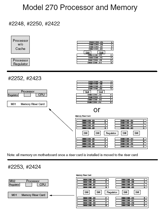
Figure 2. Model 270 system unit, processor features 22A7, 22A8, 22AA,
22AB, 23F4, 23F5, 2423, 2424, 2454

Notes:
- The model 270 system unit contains one system PCI bus with one
multi-adapter bridge. The bus number is 0001.
- There is an embedded CFIOP in the System Unit Backplane in position MB1.
- The following table provides information necessary to identify the IOP
to which IOAs are assigned. The left column indicates the domain in which
IOA assignment is allowed. The right column is used to determine the IOP to
which an IOA is assigned. The first position in the list must be an IOP. The
remaining positions may be IOPs or IOAs. IOAs are assigned to the first IOP
located to their left in the list. Although IOAs can be manually reassigned
using SST/DST, the IOA assignments return to the default order after each
IPL.
Table 4. IOA assignment rules for MB1, C01-C07
| Multi-adapter bridge domain / PCI
bridge set
|
IOA assignment rules
|
| MB1, C01 - C07
|
MB1, C07, C01, C06, C05, C04, C03, C02
|
Table 5. FRU locations and failing components for Model 270 (Processor
features 22A7, 22A8, 22AA, 22AB, 23F4, 23F5, 2423, 2424, 2454)
| Position
|
FRU name
|
Possible failing component
|
Type, CCIN, or part number (use the
Type, model, and part number list to determine the part number when
the type or CCIN are given.)
|
Remove and replace/recovery procedure
|
| C01
|
PCI card
|
IOA
|
See the
Type, model, and part number list.
|
Go to
Models 270, 800, and 810 - Cards - Concurrent.
|
| C02
|
PCI card
|
- IOP
- IOA
|
- CCIN is
2842,
2843, or
2844
- See the
Type, model, and part number list.
|
Go to
Models 270, 800, and 810 - Cards - Concurrent.
|
| C03 (Short if 2890 IXS in C04)
|
PCI card
|
- IOP
- IOA
|
- CCIN is
2842,
2843, or
2844
- See the
Type, model, and part number list.
|
Go to
Models 270, 800, and 810 - Cards - Concurrent.
|
| C04
|
PCI card
|
- Integrated xSeries Server (IXS)
- IOP
- IOA
|
- CCIN is
2890 or
2892
- CCIN is
2842,
2843, or
2844
- See the
Type, model, and part number list.
|
Go to
Models 270, 800, and 810 - Cards - Concurrent.
|
| C05
|
PCI card
|
- IOP
- IOA
|
- CCIN is
2842,
2843, or
2844
- See the
Type, model, and part number list
|
Go to
Models 270, 800, and 810 - Cards - Concurrent.
|
| C06
|
PCI card
|
- IOP
- IOA
|
- CCIN is
2842,
2843, or
2844
- See the
Type, model, and part number list.
|
Go to
Models 270, 800, and 810 - Cards - Concurrent.
|
| C07
|
PCI card
|
IOA
|
See the
Type, model, and part number list.
|
Go to
Models 270, 800, and 810 - Cards - Concurrent.
|
| MB1
|
System unit backplane
|
- Service processor
- IOP
- Card enclosure or backplane
- Clock card
- SPCN card
- HSL I/O bridge
- System unit backplane
- HSL ring connection
- Multi-adapter bridge (all)
|
282F
Note: Embedded IOP (type 284E) is exchanged with the
system unit backplane, 282F. |
Go to
Models 270, 800, and 810 - System unit backplane - MB1
|
| D01 to D06
|
Disk unit
|
Disk unit
|
See the
Type, model, and part number list.
|
Go to
Recovery procedures.
|
| D07
|
Optical device
|
Optical device
|
See the
Type, model, and part number list.
|
Go to
Models 270, 800, and 810 - Removable media - D07 and D08.
|
| D08
|
Tape unit
|
Tape unit
|
See the
Type, model, and part number list.
|
Go to
Models 270, 800, and 810 - Removable media - D07 and D08.
|
| P01
|
Power supply
|
Power supply
|
See
Final assembly -- Models 270, 800, and 810.
|
Go to
Models 270, 800, and 810 - Power supply - P01
|
| B01, B02
|
AMD
|
Air moving device (AMD)
|
See
Final assembly -- Models 270, 800, and 810 System Unit Expansion.
|
Go to
Models 270, 800, and 810 - AMD - B01 and B02
|
| NB1
|
Control panel
|
Control panel
|
247D |
Go to
Models 270, 800, and 810 - Control panel - NB1
|
| DB1, DB2, DB3
|
Device board
|
Device board |
See the
Type, model, and part number list. |
Go to
Models 270, 800, and 810 - Device board - DB1, DB2, and DB3
|
| M01
|
Memory Riser Card
|
Memory Riser Card
|
2884
|
Go to
Models 270, 800, and 810 - Cards (dedicated)
|
| M01 daughter cards
|
Memory DIMM
|
See
Figure 1. 2884 Memory card in the Memory locations and placement
rules topic.
|
3022,
3024,
3025,
3026,
3027,
3029 |
Go to
Models 270, 800, and 810 - Cards (dedicated)
|
| M02 |
Processor card |
- Processsor
- Network Interface Controller (NIC)
|
24A0 (1-way)
24A2 (2-way)
25BD (2-way) |
Go to
Models 270, 800, and 810 - Cards (dedicated)
|
| R01 |
Processor regulator card
|
Processor regulator
|
- All except type 24A2 and 25BD, use part number 04N4276
-
24A2 (2-way)
-
25BD (2-way)
|
Go to
Models 270, 800, and 810 - Processor regulator - R01
|
| M02 daughter card
|
Memory DIMM
|
See
Figure 2. Processor card with DIMM memory in the Memory locations
and placement rules topic.
|
3022,
3024,
3025,
3026,
3027,
3029 |
Go to
Models 270, 800, and 810 - Cards (dedicated)
|
| Time of day (TOD) battery on MB1 |
TOD
|
TOD
|
16G8095
|
Go to
Models 270, 800, and 810 - Time of day (TOD) battery
|
| HSL cables on the HSL ports
|
HSL cable
|
HSL connection
|
See the
Type, model, and part number list.
|
Go to
HSL cables - Concurrent.
|
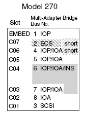
Figure 3. Model 270 system unit, processor features 23E7, 23F0, 23F1, 2452
(Processor embedded on backplane)

Notes:
- The model 270 system unit contains one system PCI bus with one
multi-adapter bridge. The bus number is 0001.
- There is an embedded CFIOP in the system unit backplane in position MB1.
- Memory DIMMS are placed in pairs when more than one DIMM is present. Use
the order A-B, C-D, E-F, then G-H.
- The following table provides information necessary to identify the IOP
to which IOAs are assigned. The left column indicates the domain in which
IOA assignment is allowed. The right column is used to determine the IOP to
which an IOA is assigned. The first position in the list must be an IOP. The
remaining positions may be IOPs or IOAs. IOAs are assigned to the first IOP
located to their left in the list. Although IOAs can be manually reassigned
using SST/DST, the IOA assignments return to the default order after each
IPL.
Table 6. IOA assignment rules for MB1, C01-C07
| Multi-adapter bridge domain / PCI
bridge set
|
IOA assignment rules
|
| MB1, C01 - C07
|
MB1, C07, C01, C06, C05, C04, C03, C02
|
Table 7. FRU locations and failing components for Model 270 (Processor
features 23E7, 23F0, 23F1, 2452)
| Position |
FRU name |
Possible failing component |
Type, CCIN, or part number (use the
Type, model, and part number list to determine the part number when
the type or CCIN are given.) |
Remove and replace/recovery procedure |
| C01 |
PCI card |
IOA |
See the
Type, model, and part number list. |
Go to
Models 270, 800, and 810 - Cards (dedicated). |
| C02 |
PCI card |
- IOP
- IOA
|
- CCIN is
2842,
2843, or
2844
- See the
Type, model, and part number list.
|
Go to
Models 270, 800, and 810 - Cards (dedicated). |
| C03 (Short if IXS in C04) |
PCI card |
- IOP
- IOA
|
- CCIN is
2842,
2843, or
2844
- See the
Type, model, and part number list.
|
Go to
Models 270, 800, and 810 - Cards (dedicated). |
| C04 |
PCI card |
- Integrated xSeries Server (IXS)
- IOP
- IOA
|
- CCIN is
2890 or
2892
- CCIN is
2842,
2843, or
2844
- See the
Type, model, and part number list.
|
Go to
Models 270, 800, and 810 - Cards (dedicated). |
| C05 |
PCI card |
- IOP
- IOA
|
- CCIN is
2842,
2843, or
2844
- See the
Type, model, and part number list.
|
Go to
Models 270, 800, and 810 - Cards (dedicated). |
| C06 |
PCI card |
- IOP
- IOA
|
- CCIN is
2842,
2843, or
2844
- See the
Type, model, and part number list.
|
Go to
Models 270, 800, and 810 - Cards (dedicated). |
| C07 |
PCI card |
IOA |
See the
Type, model, and part number list. |
Go to
Models 270, 800, and 810 - Cards (dedicated). |
| MB1 |
System unit backplane |
- Card enclosure or backplane
- Clock card
- SPCN card
- HSL I/O bridge
- Processor regulator
- Memory riser card
- System unit backplane
- HSL ring connection
- HSL controller
- Processor
- Service processor
- IOP
- Multi-adapter bridge (all)
|
25B9
Note: Embedded IOP (type 286C) is exchanged with the system
unit backplane.
OR
25BA
Note: Embedded IOP (type 286D) is exchanged with the system
unit backplane. |
Go to
Models 270, 800, and 810 - System unit backplane - MB1. |
| D01 to D06 |
Disk unit |
Disk unit |
See the
Type, model, and part number list. |
Go to
Recovery procedures. |
| D07 |
Optical device
|
Optical device
|
See the
Type, model, and part number list. |
Go to
Models 270, 800, and 810 - Removable media - D07 and D08. |
| D08 |
Tape unit |
Tape unit |
See the
Type, model, and part number list. |
Go to
Models 270, 800, and 810 - Removable media - D07 and D08. |
| P01 |
Power supply
|
Power supply
|
See
Final assembly -- Models 270, 800, and 810. |
Go to
Models 270, 800, and 810 - Power supply - P01 |
| B01, B02 |
AMD |
AMD |
See
Final assembly -- Models 270, 800, and 810 System Unit Expansion.
|
Go to
Models 270, 800, and 810 - AMD - B01 and B02. |
| NB1 |
Control panel
|
Control panel
|
247D |
Go to
Models 270, 800, and 810 - Control panel - NB1. |
| R01 |
Processor regulator card |
Processor regulator
|
04N4276
|
Go to
Models 270, 800, and 810 - Processor regulator - R01 |
| DB1, DB2, DB3 |
Device board
|
Device board
|
See the
Type, model, and part number list. |
Go to
Models 270, 800, and 810 - Device board - DB1, DB2, and DB3 |
| A through H |
Memory card |
Memory card
|
3032,
3033,
3034 |
Go to
Models 270, 800, and 810 - Memory - A through H. |
| Time of day (TOD) battery on MB1 |
TOD |
TOD |
16G8095 |
Go to
Models 270, 800, and 810 - Time of day (TOD) battery |
| HSL cables on the HSL ports |
HSL cable |
HSL connection
|
See the
Type, model, and part number list. |
Go to
HSL cables - Concurrent. |
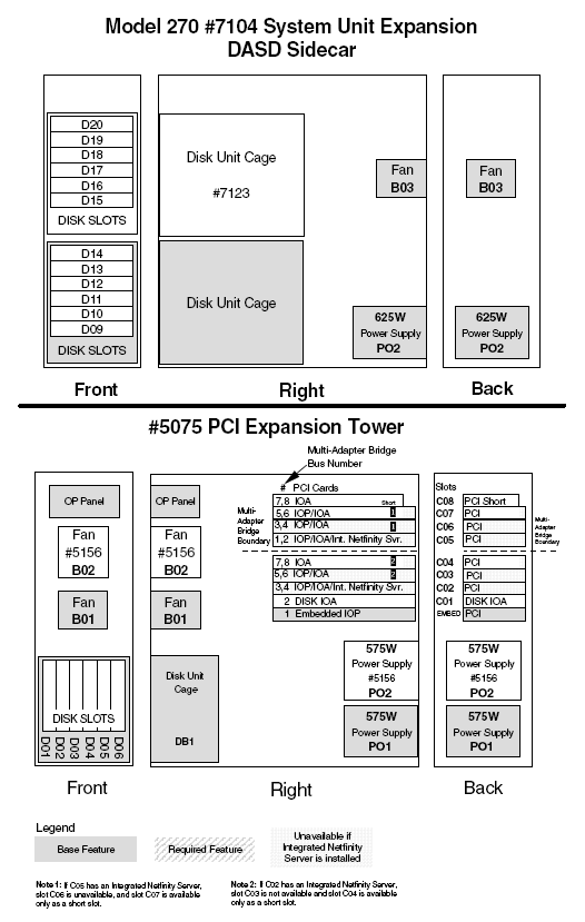
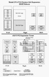
Figure 4. Model 270 FC 7104 system unit expansion

Table 8. FRU locations and failing components for the
Model 270 system unit expansion
| Position
|
FRU name
|
Possible failing component
|
Type, CCIN, or part number (use the
Type, model, and part number list to determine the part number when
the type or CCIN are given.)
|
Remove and replace/recovery procedure
|
| D09 to D20
|
Disk unit
|
Disk unit
|
See the
Type, model, and part number list.
|
Go to
Recovery procedures.
|
| DB2 and DB3
|
Device board
|
Disk unit backplane
|
See the
Type, model, and part number list.
|
Go to
Models 270, 800, and 810 - Device board - DB1, DB2, and DB3.
|
| P02
|
Power supply
|
Power supply
|
See
Final assembly -- Models 270, 800, and 810 System Unit Expansion.
|
Go to
Models 270, 800, and 810 - Power supply - P02.
|
| B03
|
AMD
|
AMD
|
04N5698 |
Go to
Models 270, 800, and 810 - Air moving device - B03. |
|